Go to Accessory Manager in the left sidebar and click on the (+) button to configure the accessories you wired to the inputs and outputs. Supported accessory types are shown below.
- Lightbulb, Switch, Outlet, Valve - For controlling lights and appliances
- Window Covering - For controlling window blinds and shades
- Lock - For controlling door locks
- Garage Door - For controlling garage doors
- Contact, Occupancy, Motion Sensor and Programmable Switch - For detecting open/closed states, occupancy, motion, and momentary switches
- DALI Light - For controlling DALI lights
The following sections provide detailed setup instructions for each device type. Follow the steps for your specific accessory.
¶ Lightbulb, Switch, Outlet, Valve
Assuming a Lightbulb is wired to Relay 1 (see Wiring Example 230V Loads), as well as a Push Button to Input 1 we can configure the Accessories as follows:
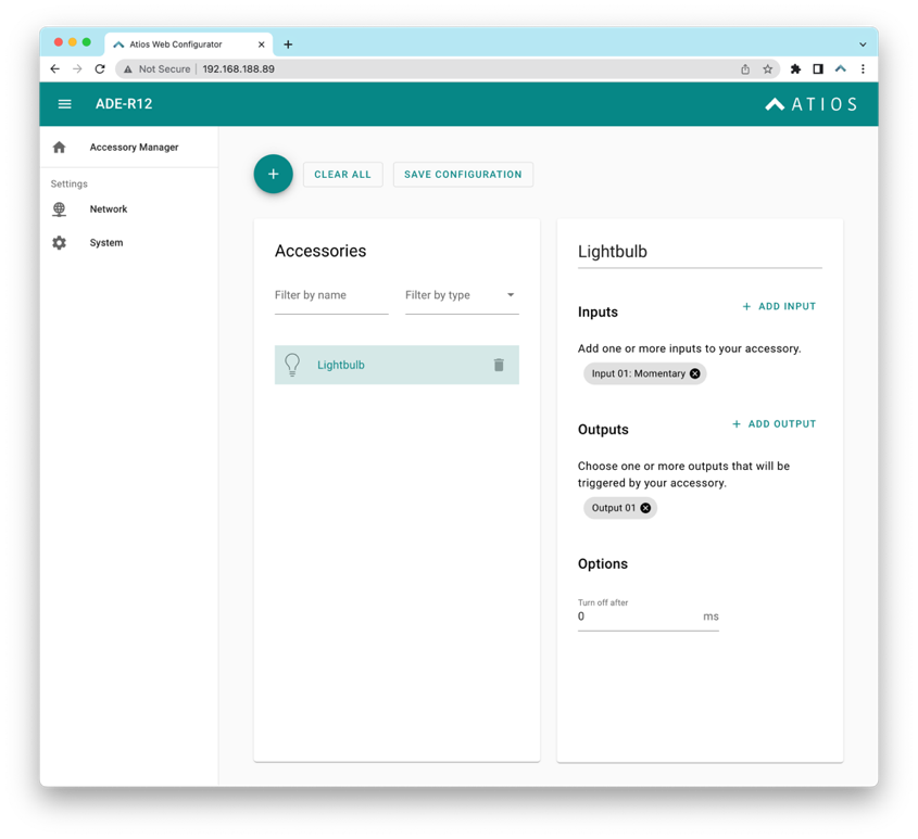
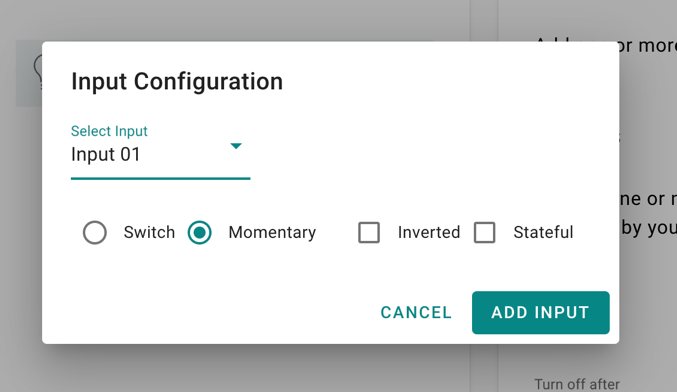
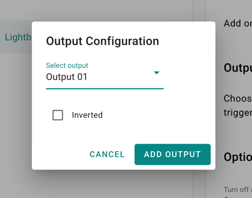
One input can be assigned to multiple outputs, as well as multiple outputs to a single accessory. A Switch, an Outlet and a Valve are configured similarly.
¶ Additional Settings
| Name | Value | Description |
| Input | Switch | An input device that sends a constant HIGH until being pressed again. SmartCore will react on both changes LOW → HIGH, and HIGH → LOW |
| Input | Momentary | An input device that sends a momentary HIGH until released. SmartCore will react only on change LOW → HIGH |
| Input | Inverted | In case of Momentary reacts to change HIGH → LOW |
| Input | Stateful | In case of Switch only reacts to LOW → HIGH, can be reversed to HIGH → LOW when "Inverted" is activated. |
| Output | Inverted | Inverts the Relay from Normally Open to Normally Closed |
| Option: Turn off after | Time in milli seconds | Load will be automatically switched off after the set time passes |
¶ Window Covering
Assuming the electric motor of a Window Covering is wired to Relay 1 and Relay 2 (see Wiring Example Window Covering), as well as a Push Button to Input 1 and 2 we can configure the Accessories as follows:
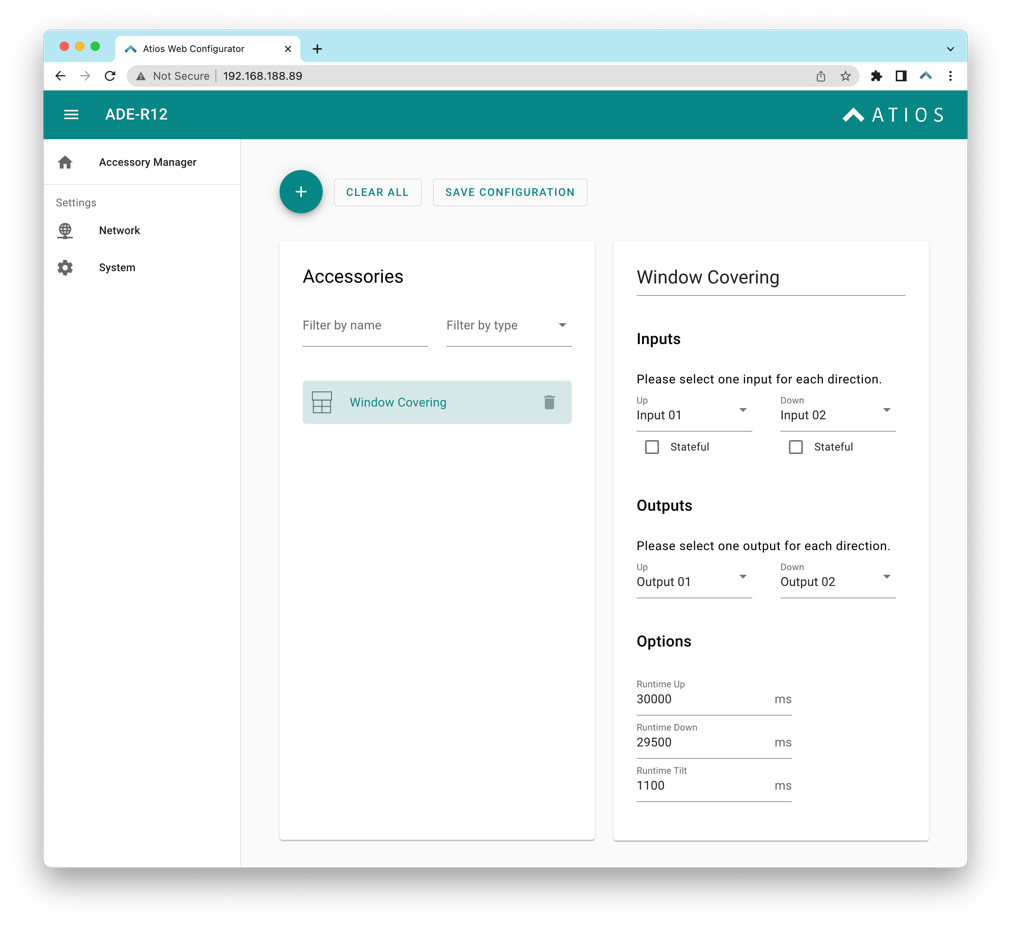
The motor directions UP and DOWN can be inverted by switching the outputs, vice versa for the inputs.
¶ Additional Settings
| Name | Value | Description |
| Runtime Up | Time in milli second | Enter the time the Window Covering needs to completely drive while opening. |
| Runtime Down | Time in milli second | Enter the time the Window Covering needs to completely drive while closing (can be different to opening). |
| RunTime Tilt | Time in milli second | Leave empty if the Window Covering has no Slats. Otherwise enter the time they need to go from -90° to +90° |
¶ Lock
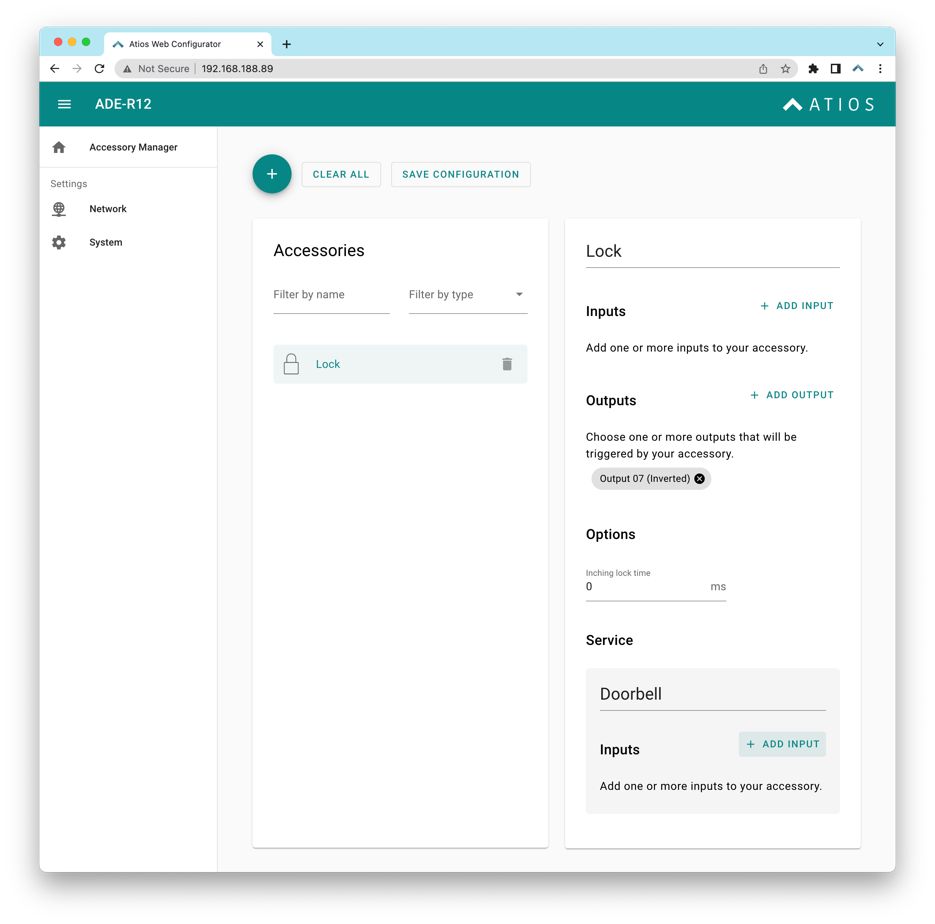
Assuming the motorized door lock actuator is wired to Relay 7 (see Wiring Example 24V Loads) and needs to be inverted, we can configure the Accessories as follows:
¶ Additional Settings
| Name | Value | Description |
| Options: Inching lock time | Time in milli second | Relay will be automatically switched off after the set time passes |
| Doorbell | Input | If a doorbell is connected to one of the Inputs, the Home App will issue a Push Notification that the doorbell was rung. And HomePods will play a Doorbell sound. |
¶ Garage Door
Usually a garage door is controlled via an impulse between two wires. Connect these wires to the two terminals of for example Relay 1. Additionally you will need a door sensor that indicates if the Garage Door is fully opened or closed, usually by a magnetic reed contact. Assuming this is wired to Input 1 configure the Garage Door as follows:
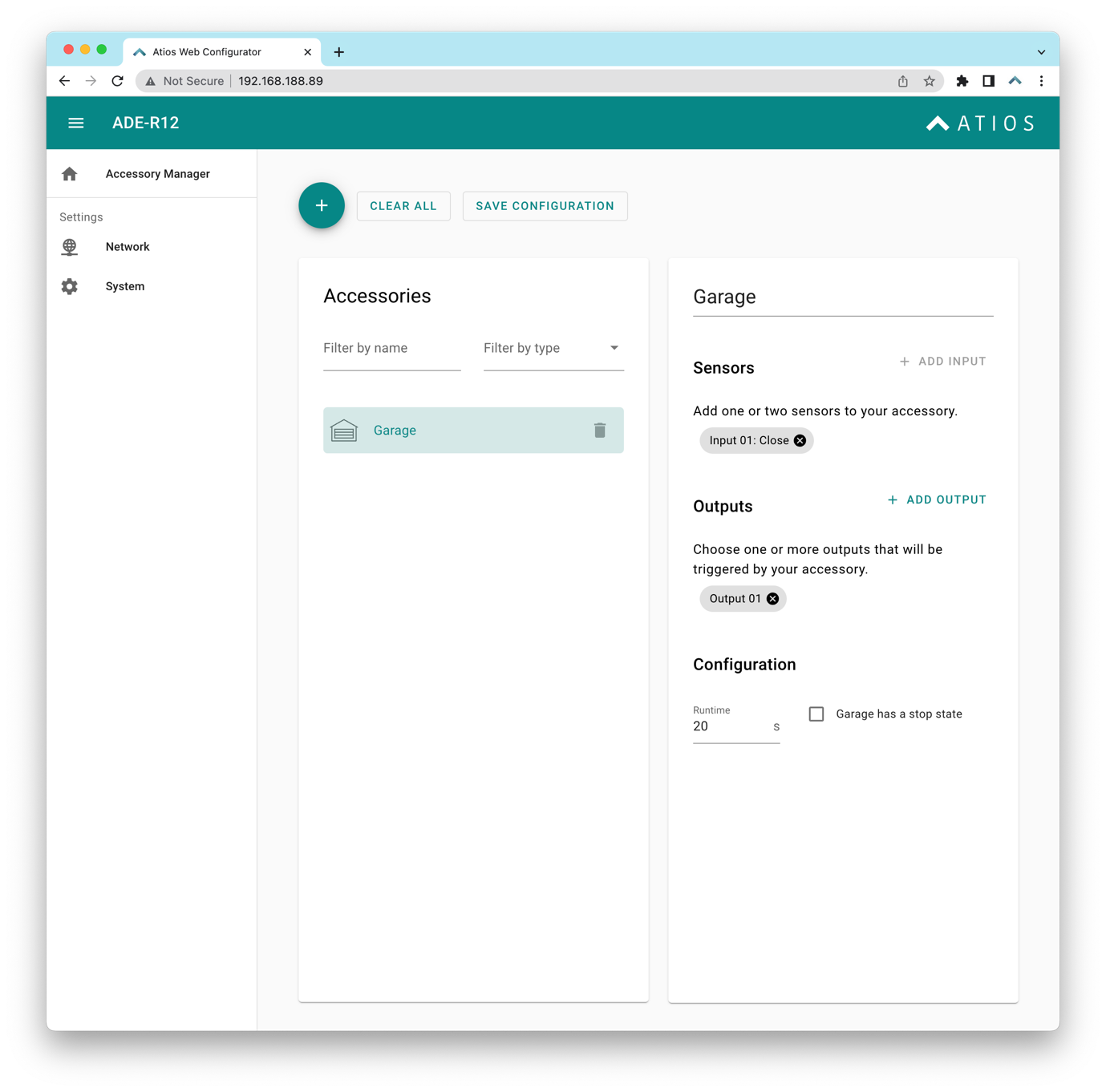
Multiple Door sensors (one for Closed, one for Open) are supported. If only a single sensor is used, fill in the time in seconds that the Garage needs to completely open to calculate the state.
¶ Additional Settings
| Name | Value | Description |
| Runtime | Time in seconds | The status of the garage will be automatically computed using the runtime and the sensor. |
| Stop State | Checkbox | Check this box if your garage changes with a button press between the states OPENING – STOPPED – CLOSING. |
¶ Contact, Occupancy, Motion Sensor and Programmable Switch
Assuming you have wired a door or window contact sensor to Input 1 configure the accessory as follows:
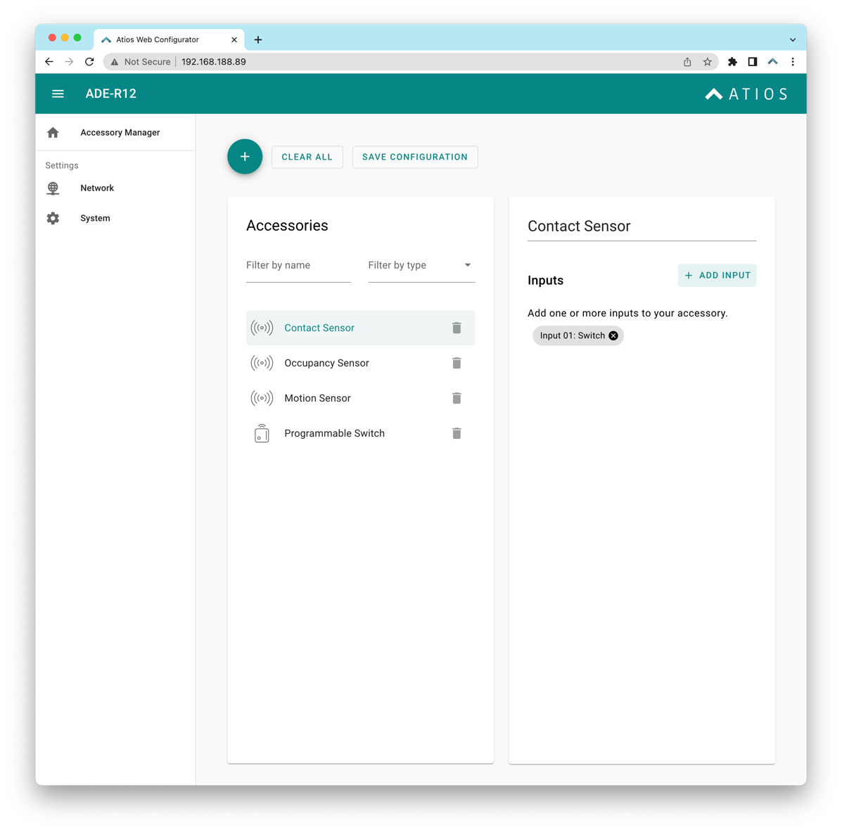
Similar for an Occupancy or Motion Sensor. A Programmable Switch can later in the Apple Home App be assigned to control other accessories or Scenes. Double and long press will be supported soon.
¶ Additional Settings
| Name | Value | Description |
| Input | Stateful Switch | A sensor that sends a constant HIGH when being triggered. Will show in Apple Home as active when HIGH and inactive when LOW. |
| Input | Momentary | Only for Programmable Switch, triggers a Single press when changing from LOW → HIGH |
| Input | Inverted | To invert the state of a Sensor when set as "Switch". |
| Input | Stateful | In case of Switch only reacts to LOW → HIGH, can be reversed to HIGH → LOW when "Inverted" is activated. |
¶ DALI Light
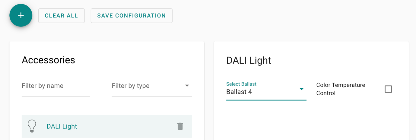
This allows to control any DALI ballast (Lamp, LED Strip etc.) with Apple Home. If there are multiple DALI ballasts connected to your DALI Bus they must be commissioned priorly with their respective DALI addresses, so they can be controlled separately. Commissioning is done either on the DALI ballast if it has a display, or with third-party DALI USB or network interfaces and software. The DALI Bus can be powered externally, or with the integrated DALI power supply from Atios SmartCore. Only use either or, do not use both at the same time. Imagine you have a DALI ballast installed and configured as follows:
| DALI Address | Description |
| Adr 4 | Dimmable Ceiling Lamp |
Add a DALI Light in Accessory Manager as follows:
