
Installation
The DALI AC Dimmer is an in-wall device. It fits into a flush-mounted installation box and measures 45.5 × 45 × 20.3 mm.
Connections
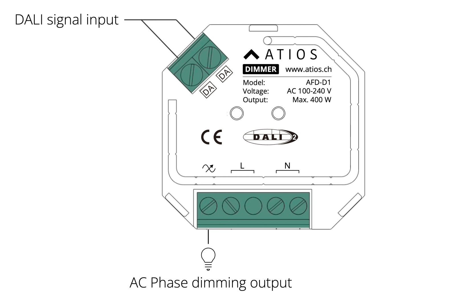
- Mains and output: a single four-pole screw-terminal strip, labelled L, L, N, N. Two of the terminals, marked with the load symbol (⊗), are the dimmed output to your load; the other two are the mains input. Follow the L/N marking silkscreened on the device for each pair.
- DALI bus or push switch: the two-pole DA terminal. Wire a DALI bus here, or a single conventional push switch (8-230 V~). The terminal accepts either, not both at once.
WARNING
Do not install or wire the device with power applied.
Mounting and wiring
- Wire the mains supply to the input L/N terminals.
- Wire your load to the output L/N terminals (marked ⊗).
- Wire the DALI bus, or a single push switch, to the DA terminal.
- Fit the dimmer into the flush-mounted box.
Push switch wiring
The DA terminal is dual-purpose: it reads either a DALI bus or a single push switch, never both at the same time. Wire the switch across the two DA terminals, with no more than 80 m of cable between the switch and the dimmer.
To operate the dimmer from several locations, wire the push switches in parallel across the same DA terminal, each within 80 m of the dimmer.
Load limits
- Up to 10 dimmable drivers or luminaires in parallel. More can draw enough inrush current at power-on to damage the dimmer.
- Up to 80 m of cable between the dimmer and the load.
- This is a trailing-edge (reverse-phase) dimmer. Check that the connected load supports reverse-phase control before wiring it (see the load's own documentation). Dimmable LED lamps and drivers, incandescent and HV halogen lighting, and LV halogen with an electronic transformer are all supported; see the Datasheet for the wattage limit per load type and supply voltage.