
Installation
The DALI-2 Button Coupler is an in-wall device. It fits into a flush-mounted installation box behind the buttons it serves and measures 40.5 x 28 x 14.5 mm.
Connections
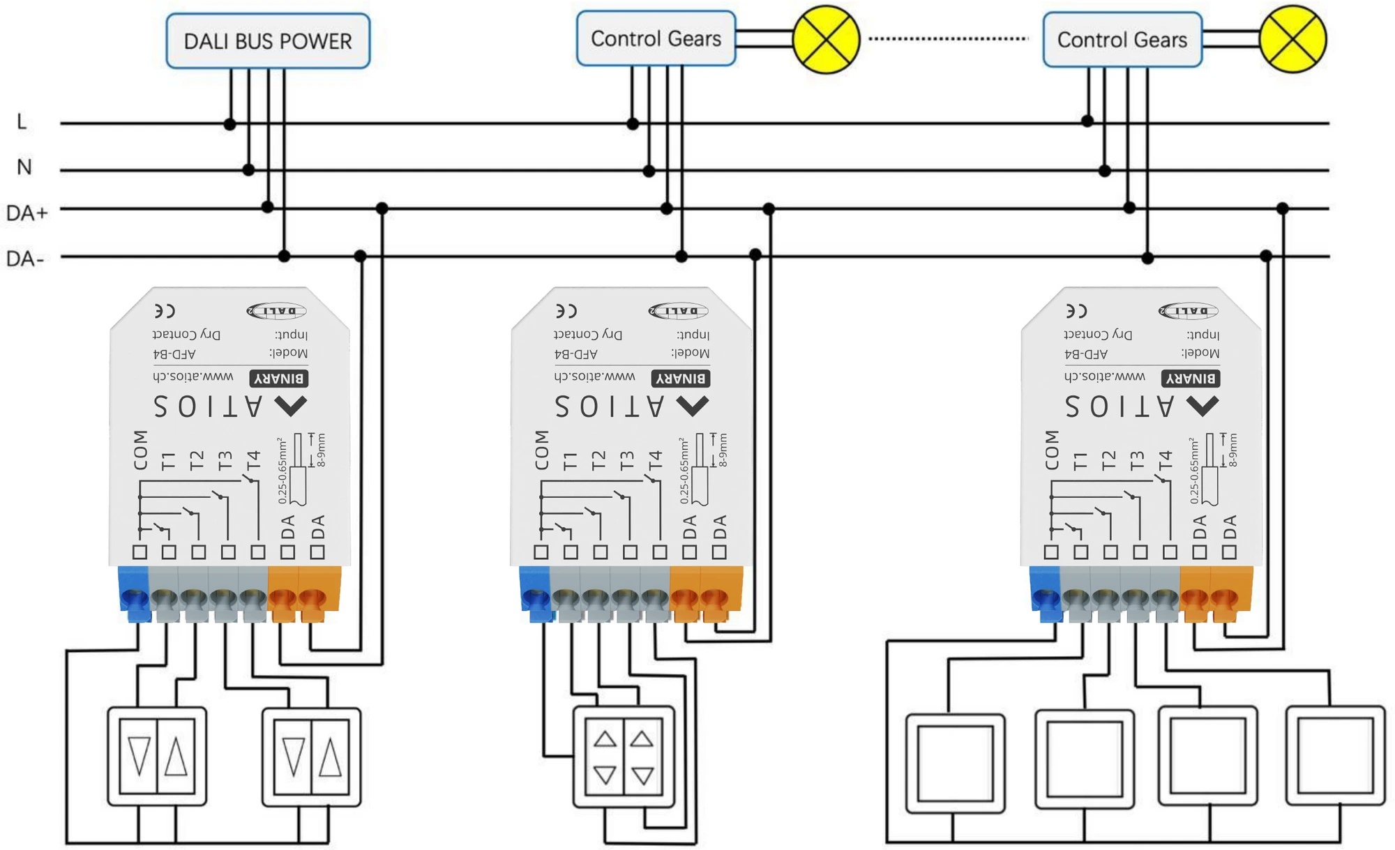
- Buttons: terminals T1, T2, T3 and T4, each switched against the shared COM terminal.
- DALI bus: the two DA terminals. Polarity does not matter, either wire can go to either terminal.
All terminals are spring type. They take 0.25 to 0.65 mm² solid or fine wire, or 0.2 to 0.5 mm² with a wire end ferrule. Strip 8 to 9 mm. Connect one wire per terminal.
Mounting and wiring
- Wire the DALI bus to the two DA terminals.
- Wire each button between its input terminal and COM.
- Fit the coupler into the flush-mounted box behind the buttons.
The DALI bus needs its own power supply. The bus input tolerates mains voltage, so the device survives being wired to the wrong terminals, but do not rely on that.
Several couplers share one DALI line. Each sits on the same pair of bus wires as the control gear it operates, alongside the DALI power supply.
WARNING
The button wiring must not exceed 50 cm per input. These are the leads from the coupler to the buttons in the same box, not the DALI bus itself.
TIP
The DALI signal is not a SELV circuit. The installation rules for low voltage apply, and the work must be done by a qualified electrician with the system de-energised.
DALI line limits
The voltage drop across the DALI line must stay below 2 V at the maximum line length of 300 m and the maximum bus load of 250 mA. Standard low-voltage installation cable is sufficient, no special cable is needed.
For the full electrical ratings, see the Datasheet.