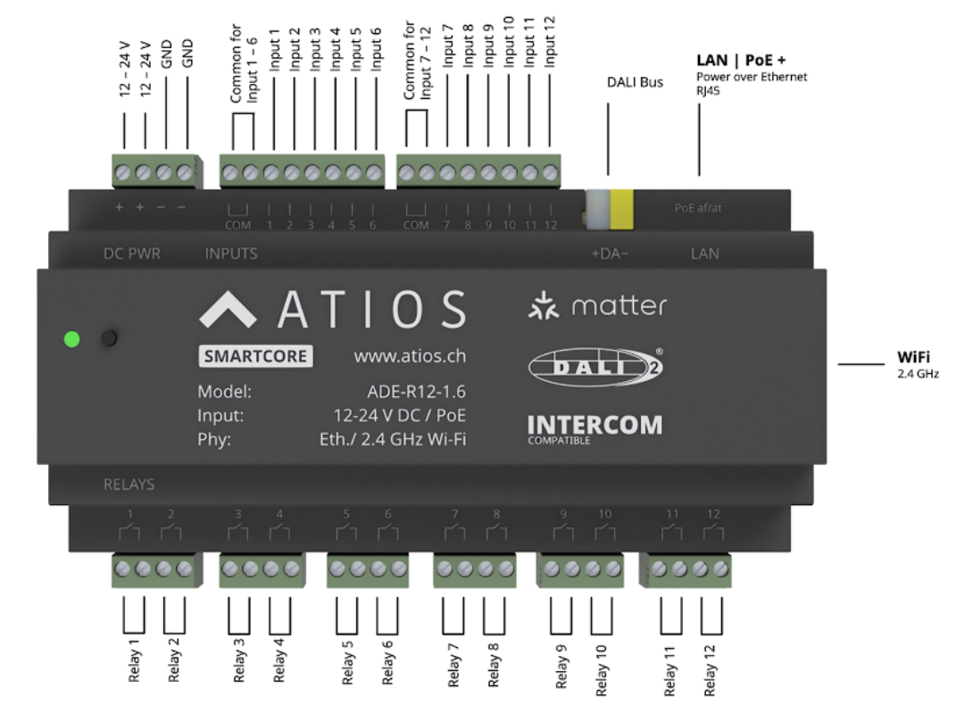
Wiring
| Count | Type | Rating | |
|---|---|---|---|
| Outputs | 12 relays | Potential-free (dry contact) | 16 A; voltages and phases are freely mixable across relays |
| Inputs | 12 digital | Opto-isolated, 2 groups of 6 (COM per group) | 12 V DC – 230 V AC, use one voltage type per group (all DC or all AC) |
Inputs, outputs and the device's power supply are electrically isolated, so they don't need to share a breaker, neutral, or phase.
1. Power
Power over Ethernet (PoE)
Connect an Ethernet cable from a switch port to the LAN terminal.
External 12–24 V DC
- Mount a 12–24 V DC DIN-rail PSU and wire L and N to the PSU input.
- Wire PSU +V to DC PWR (+), GND to DC PWR (−).
2. Outputs
230 V AC loads
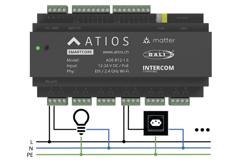
- Wire the supply phase (L) to the relay input.
- Wire the load to the relay output.
- Return the load through neutral (N); bond metal loads to PE.
24 V DC loads
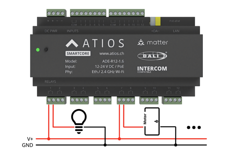
- Wire V+ to the relay input.
- Wire the load to the relay output and return it to GND.
Window coverings (2 relays per motor)
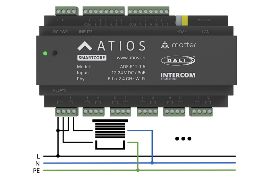
- Pick two adjacent relays, one for up and one for down.
- Wire the supply phase to both relay inputs.
- Wire the motor's "up" lead to one relay output, the "down" lead to the other.
- Return the motor through neutral.
Any bi-directional load (door operator, valve actuator) follows the same pattern.
3. Inputs
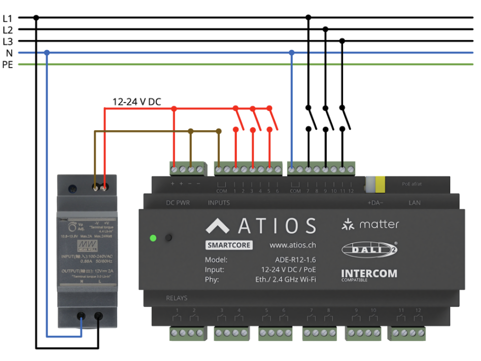
DC inputs (12–24 V DC)
- Connect the group's COM to the DC supply.
- Wire the switch or contact between the DC line and an input terminal.
AC inputs (230 V AC)
- Connect the group's COM to N.
- Wire the supply phase through the switch or contact to the input terminal.
L1, L2 and L3 can be mixed across inputs in the same group.
Powering SmartCore over PoE
- Leave the DC PWR terminals unconnected. Do not feed DC and PoE at the same time.
- Connect the LAN port to a PoE switch or a PoE injector.
If you still want low-voltage DC inputs while running on PoE, you need a separate DC source for the input COM.
4. DALI
The DALI bus (DALI+ / DALI−) carries lighting commands and sensor events. The SmartCore is the DALI-2 master and addresses up to 64 devices (0–63) and another 64 DALI ensors.
WARNING
Bus power: Either use the integrated 250 mA supply or an external DALI PSU, never both.
DALI lighting
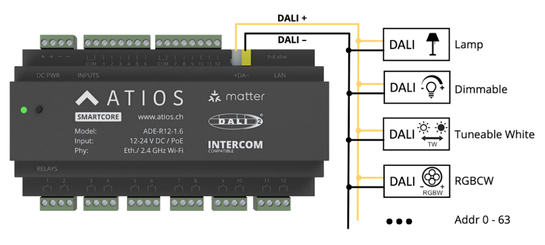
Wire DALI+ from SmartCore to DALI+ on each fixture and DALI− from SmartCore to DALI− on each fixture.
DALI sensors and input devices
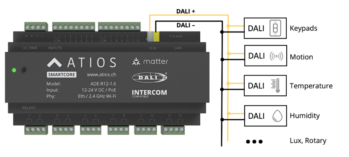
DALI sensors like keypads, motion sensors, temperature controls etc. are wired onto the same DALI bus as DALI lighting.