
Installation
The DALI AC Dimmer DIN is a DIN-rail device (90 × 66 × 18 mm) for the electrical cabinet. It mounts on a 35 mm rail (EN 60715).
Connections
- Mains input: terminals N and L (top pair).
- Output: terminals O and N: O is the switched, dimmed live to your load; N is neutral, bridged straight through from the mains input.
- DALI bus or push switch: the two DA terminals. Wire a DALI bus here, or a single conventional push switch. The terminal accepts either, not both at once.
All terminals take 0.75-2.5 mm² (18-12 AWG), strip length 5.5-7.5 mm.
WARNING
Do not install or wire the device with power applied.
Mounting and wiring
- Clip the dimmer onto the DIN rail.
- Wire the mains supply to N and L.
- Wire your load to O and N.
- Wire the DALI bus, or a single push switch, to the DA terminals.
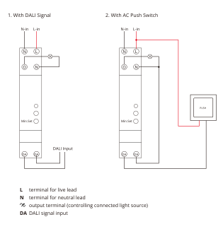
Push switch wiring
The DA terminal is dual-purpose: it reads either a DALI bus or a single push switch, never both at the same time. Wire the switch across the two DA terminals, in place of the DALI bus.
Load limits
The dimmer supports resistive, capacitive and inductive loads: dimmable LED lamps and drivers, incandescent and HV halogen lighting, and LV halogen with an electronic transformer. See the Datasheet for the wattage limit per load type and supply voltage.
The dimmer works on the trailing edge (reverse phase). Check that the connected load is suitable for trailing-edge dimming before wiring it.