
Installation
The DALI Relay Module is an in-wall device. It fits into a standard wall box and measures 45 × 45.5 × 20.3 mm.
Connections
- DALI bus: the two-pole DA terminal, the DALI signal input. The module takes its power from the DALI bus.
- Relay output: the two terminals marked with the relay symbol. The contact is normally closed (N.C.), and its factory default status is closed.
- NC terminals: NC means No Connection. Do not confuse it with N.C. (normally closed) on the relay output.
WARNING
Do not install the device with power applied. Do not expose the device to moisture.
Wiring
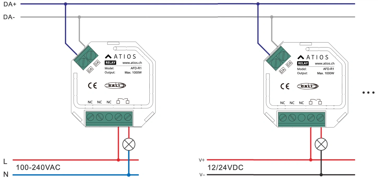
The relay output switches one load circuit:
- 100-240 V AC load: wire the relay output between L and the load, and the other side of the load to N.
- 12/24 V DC load: wire the relay output between V+ and the load, and the other side of the load to V−.
The relay module can also control one standard contactor via DALI.
Load limits
| Load type | Examples | 230 V AC | 110 V AC |
|---|---|---|---|
| Resistive | Conventional incandescent and halogen light sources | 1000 W | 500 W |
| Capacitive | Fluorescent tube lamps (compact or with electronic ballast), electronic transformers, LED | 300 W | 150 W |
| Inductive | Ferromagnetic transformers | 1000 W | 500 W |
The maximum switching voltage is 250 V AC or 30 V DC. The maximum current is 4.3 A for resistive loads, 1.3 A for capacitive loads and 4.3 A for inductive loads.