
Installation
The DALI LED Driver is a surface-mount enclosure, 244 × 64 × 32 mm, fixed in place with a screw at each end. Each end has three screw-hole positions to choose from.
Connections
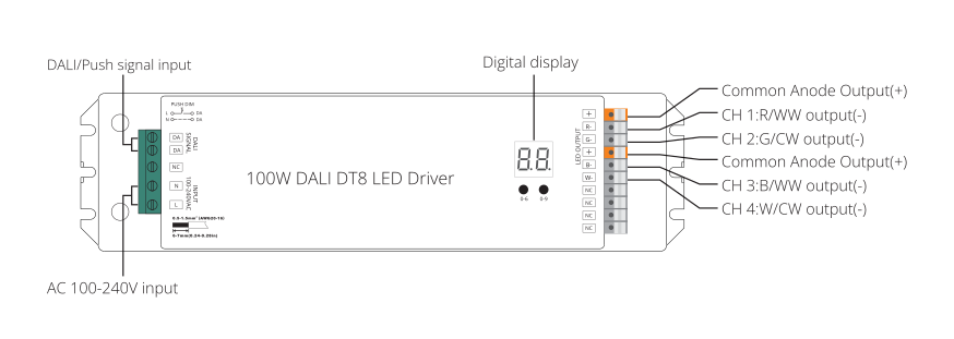
Input, on the left-hand terminal block:
- DA, DA: DALI bus or push switch (dual-purpose, see below).
- N, L: mains input, 100-240 V AC.
Output, on the right-hand terminal block (LED OUTPUT):
- +, R-, G-, +, B-, W-: the four channel outputs and their two shared common-anode (+) terminals: CH1/CH2 share the first +, CH3/CH4 share the second. Which terminals you wire, and how, depends on the device type you select. For the wiring per type, go to Device Types.
- NC: not connected.
All terminals take 0.5-1.5 mm² (AWG 20-16), strip length 6-7 mm.
WARNING
Do not install or wire the device with power applied.
DALI bus or push switch
The DA terminal is dual-purpose: it reads either a DALI bus or a single push switch, never both at the same time. In push-switch mode, only the first channel pair (CH1/CH2) responds to the switch; click to switch on or off, press and hold to dim.
Mounting
Choose one of the three screw-hole positions at each end and fix the driver in place with a screw through each.