
Mounting & Wiring
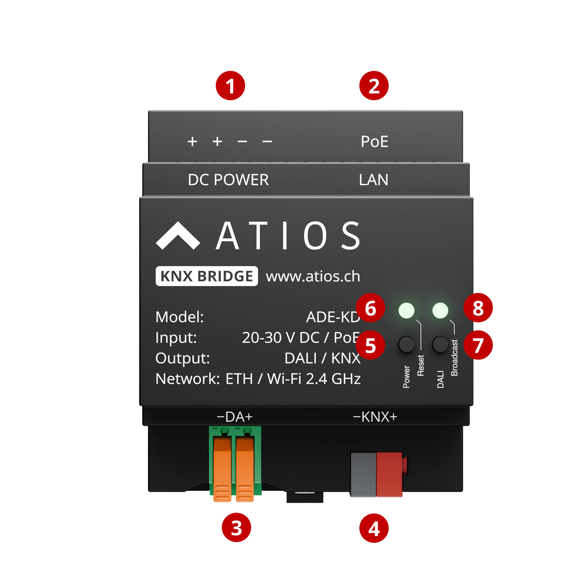
- 1DC POWER terminals, 20-30 V DC
- 2LAN port, Power over Ethernet
- 3DALI bus terminals (−DA+)
- 4KNX TP bus terminals (−KNX+)
- 5Reset button: reboot, factory reset, KNX programming mode, safe mode
- 6Power LED, system status
- 7DALI button, broadcast on/off for all DALI lights
- 8DALI status LED, bus status
- Mount the KNX Bridge to the DIN Rail in the electrical cabinet.
- Connect power via PoE to Ethernet port ②, or connect a 20-30 V DC supply to terminal ①. PoE powers the device and provides network connectivity, no separate DC supply needed.
- Connect the KNX TP Bus to terminal ④. Observe polarity.
- If using DALI lights, connect the DALI Bus to terminal ③. Connect Yellow to DALI ⊕ and White to DALI ⊖.
- For network access, use a PoE Ethernet cable ② for LAN, or configure WiFi via Network Settings using a separate DC power supply ①.
WARNING
If using the built-in DALI power supply, ensure no other power supply is connected to the DALI bus. You can enable the internal PSU under System Settings → DALI.