
Atios KNX Universal8 ADK-R8 Datasheet
EAN 7649988416620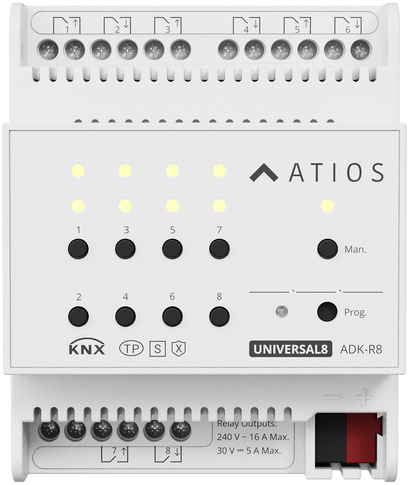
Technical Specifications
| KNX bus | 21-30 V DC via the KNX bus, <10 mA at 24 V, <9 mA at 30 V, <270 mW; charging current <22 mA |
| KNX Secure | Supported; configured via ETS5 or higher |
| Outputs | Max. 8 switch / 4 shutter AC / 2 shutter DC / 2 fan coil / 2 valve outputs, freely mixable |
| Terminals | KNX bus terminals; screw output terminals 0.2-2.5 mm², 0.4 N·m |
| Relay rating (AC) | 240 V AC, max. 16 A |
| Relay rating (DC) | 30 V DC, max. 5 A |
| Relay life | Mechanical >1 × 10⁶, electrical (resistive) >5 × 10⁴ |
| Size and weight | MDRC, 35 mm DIN rail (EN 60 715), 72 × 90 × 64 mm, 0.30 kg |
| Enclosure | Plastic, beige |
| Protection | IP 20, EN 60 529 |
| Ambient temperature | −5 °C to +45 °C (operation), −25 °C to +55 °C (storage), −25 °C to +70 °C (transport) |
| Humidity | < 93 %, non-condensing |
| Control | 8 channel buttons + Manual/Auto + Prog buttons; matching status LEDs |
| Certifications | CE, RoHS, KNX Secure certified, ISO 9001:2015 |
Application area and features
- Universal KNX actuator with 8 freely configurable output channels for switch, shutter (AC/DC), fan coil, or valve control.
- KNX Secure, configured via ETS5 or higher.
- Switch outputs: time functions, 8 scenes, logic, status response, forced operation.
- Heating actuator mode: switch outputs drive thermal heating valves directly (PWM or 2-point), without a separate controller.
- Shutter AC/DC outputs: up/down, position 0-100%, louvre adjustment, 8 scenes, automatic sun protection, safety function, two modes (venetian blind / shutter).
- Fan coil outputs: up to 3-level fan speed, step-switch and steering-switch modes, automatic, manual and forced operation.
- Valve outputs: continuous (3-point), PWM and 2-point switching; valve-curve correction and automatic cleaning for continuous valves.
Wiring
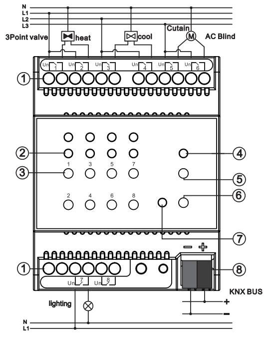
- 1Output terminals. The symbols above each terminal block show the wiring for that output type.
- 2Status LEDs for the outputs, one above each button
- 3Manual operation buttons for outputs 1 to 8
- 4Man./Auto. status LED
- 5Man./Auto. switch button
- 6Programming button
- 7Programming LED
- 8KNX bus connection terminal